Axis 25734 User Manual
Browse online or download User Manual for Security cameras Axis 25734. 1 - Axis
- Page / 12
- Table of contents
- BOOKMARKS
Summary of Contents
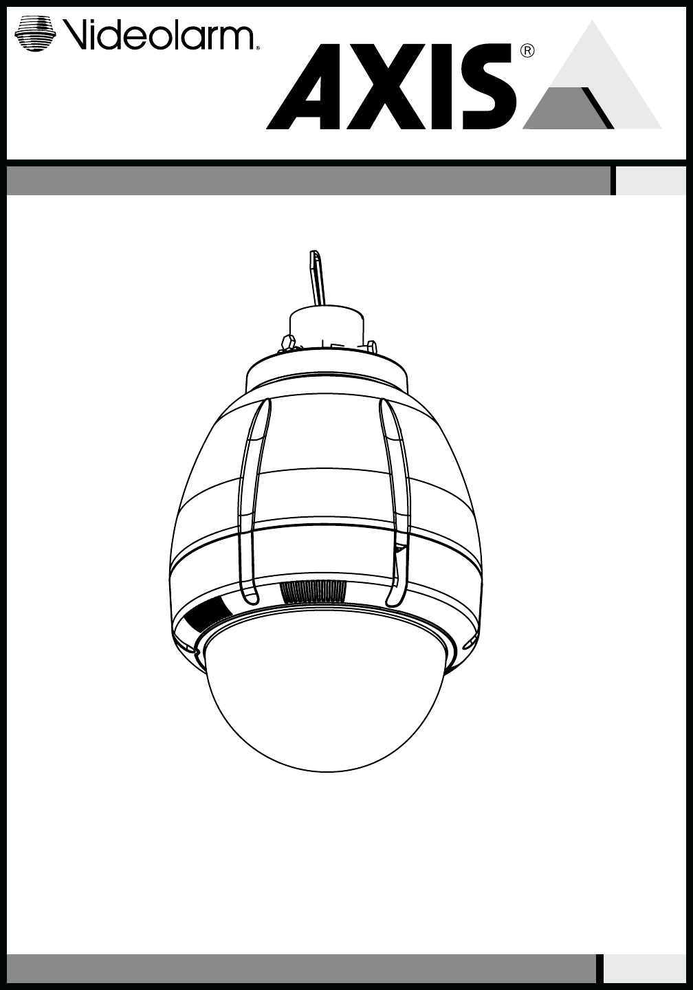
81-IN6222R3PRODUCT INSTRUCTIONSMODEL:25734C O M M U N I C A T I O N SforBefore attempting to connect or operate this product,please read these instruc
Remove 24Vac to 12VDC power board located inside of housing, attach 2 “L ” brackets to mounting plate. Connect Pan tilt with hardware provided.• Q
TabConnect Lanyard to trim ring assembly.• Conecte el acollador con el montaje del anillo del ajuste.• Reliez la lanière à l'anneau d'équi
25734Replacement Parts ListPart Number Description1 RPFD7015 Lower Trim Ring2 RC7AT Tinted Replacement CapsuleRC7AC Clear Replacement Capsule3 RPFD703
!!SAFETY PRECAUTIONSIMPORTANT SAFEGUARDS1. Read Instructions - All the safety and operating instructions should be read before the unit is operated.2
Content of BoxHardware Packet25734 Outdoor Housing (Clear)Power 24VACClass 2 Only Total Power: 89 Watts Heater: 50 Watts Blower: 2 WattsCamera Powe
1 Securely mount bracket to wall. Pull wiring through bracket and position grommet as shown. • Con seguridad soporte del montaje a emparedar. Tire
5 Loop the lanyard over the set screw to temporarily hold housing.• Coloque el acollador sobre el tornillo de presión para celebrar temporalmente la
RJ45RJ4524VAC1234CameraCameraHeater/BlowerHeater/BlowerRedOrangeYellowGreenSNC-RZ25/SNC-RZ55018 Watts 25 Watts 52 Watts 1/01234Alarm 1Alar
182685 Mounting PlateMounting HoleMounting HoleMounting HoleAxis 214(52mm) 2"Captive Screw(3) #8 x 3/8” Install the camera to the moun
TabLoosen ScrewAXIS 231-232D18 Loosen the screw to the right of the tab by approximately (5) turns.• Afloje el tornillo a la derecha de la lengüeta
3mm Screw Power BoardConnection Module20 This is what the typical path of illumination will look like with the setting at 30 degrees.• Para quitar a
Related products and manuals for Security cameras Axis 25734
 (2 pages)
(150 pages)
(4 pages)
(2 pages)
(150 pages)
(4 pages)
 (2 pages)
 (2 pages)
(3 pages)
(28 pages)
(45 pages)
(2 pages)
(3 pages)
(28 pages)
(45 pages)
© 2020, manymanuals.com. All rights reserved. | 0.638 s |
 Manymanuals.com
 Manymanuals.de
 Manymanuals.fr
 Manymanuals.it
 Manymanuals.pl
 Manymanuals.cz
 Manymanuals.es
 Manymanuals-pt.com
Comments to this Manuals